How Ground Penetrating Radar (GPR) improves road investigations.
There are more than 64 million kilometres of roads in the world, all of different age and condition, some paved and some unpaved. The road infrastructure is important for innumerable reasons and needs to be maintained to a certain level to ensure safe access, both for private and public transportation.
Today, most inspections and maintenance plans are based on invasive investigations with drilling or sampling of the roadbed at discrete locations; this gives precise information but only at those points. With a growing road network requiring maintenance due to age and use, the need for information on its condition is increasing. Geophysical methods can then be a suitable solution to create a more comprehensive picture of the internal structure of our roads.


Using GPR to detect asphalt and reinforcement layers in roadways
GPR (Ground Penetrating Radar) is a non-destructive investigation method that will provide greater data coverage compared to traditional, point-by-point, geotechnical investigations such as drilling or digging, which makes it a very cost-efficient method for road investigations.
Above: We see a 200m road section displaying the different road layers from the top level Asphalt down to the Subgrade, (down to a depth of 2.0 m).
What's the right GPR antenna for Road Investigation?
What frequency to use depends on the application, and what resolution and depth is required. For road embankment mapping (with total thickness and internal layers) frequencies around 450MHz to 2.3GHz arequite convenient. If the geology underneath the road are of interest as well, frequencies of 100 to 250MHz can be used.
Most often it is efficient to usetwo antenna frequencies or moreat the same time, providinghigh resolution for thin asphalt layers with a high frequency antenna and a good overview of the total road embankment with a lower frequency antenna. As seen in the table below resolution changes with antenna frequency but this is also true for an increasing depth, meaning that objects need to be larger, at depth, to be identified.
Note! It is important to remember that this is only a guide and the results at a certain site will very much depend on local conditions, i.e. the specific electrical properties of the site investigated.
GPR Antenna Frequency/Resolution/Depth
| Antenna Frequency (MHz) | Suitable Target Size (m) | Approx. Depth Range (m) |
| 100 | 0.1 | 2-15 |
| 160 HDR | 0.16 | 1-12 |
| 250 | 0.05 | 1-10 |
| 450 HDR | 0.04 | 1-6 |
| 500 | 0.04 | 1-5 |
| 750 HDR | 0.03 | 0.4-3 |
| 800 | 0.03 | 0.4-2 |
| 1200 | 0.02 | 0.3-2 |
| 1600 | 0.015 | 0.2-1 |
| 2300 | 0.005 | 0.1-0.9 |
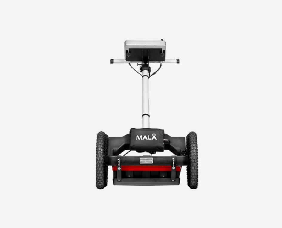
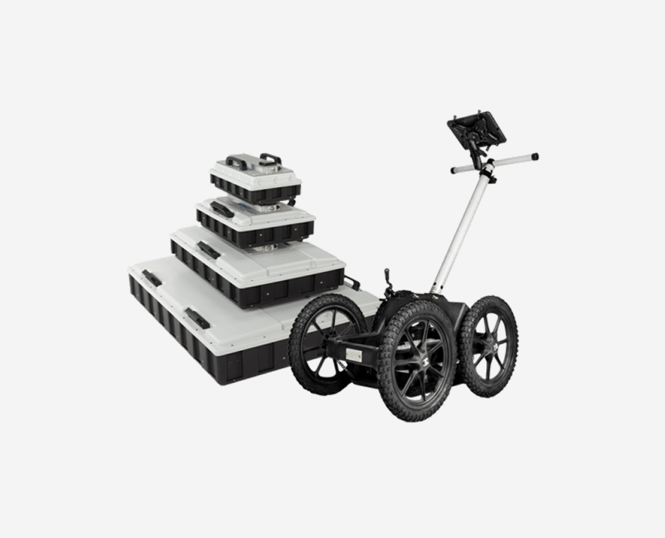
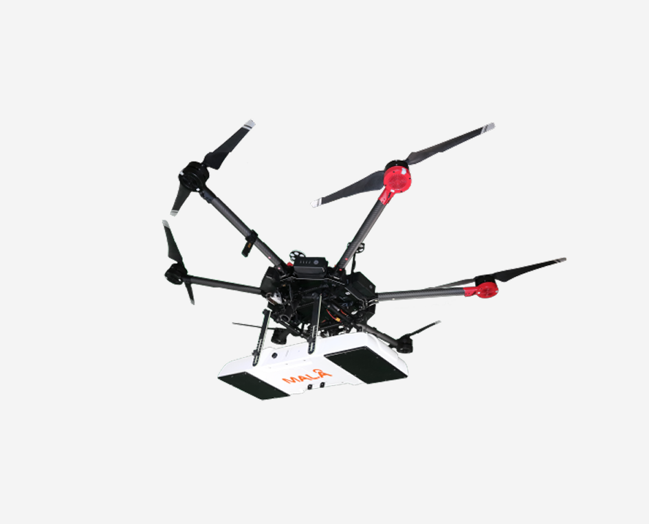
GPR measurements for road applications are most often done by pulling the antennas in a cart along the ground, which can be efficient for smaller areas. For longer investigation lines, Guideline Geo also provides a convenient cart, the RoadCart, for holding 1-3 antennas behind a vehicle. The MALÅ MIRA HDR can be an efficient tool if wider and very precise investigations are needed. As well as the MALÅ MIRA Compact with the Tow Hitch Carrier.
During measurements, the position of the GPR antenna is tracked by an external or internal GPS for precise positioning of your investigation results.

GPR for different road applications
Suitable applications to solve with GPR within the area of roads are:
- Mapping asphalt thickness
- Investigate internal road layers
- Mapping geology underneath the road (such as bedrock, peat, soil layers)
- Locating utilities within the road and/or embankment
- Mapping piled decks underneath the road embankment
- Detecting voids within the road structure
- Mapping boulders/stones within the road embankment
- Mapping ground frost, moisture
The Tow Hitch Carrier with a MALÅ MIRA Compact
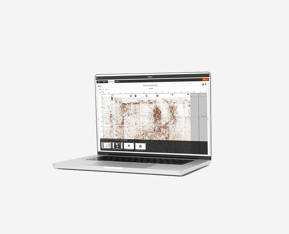
GPR investigation results with 2D measurements
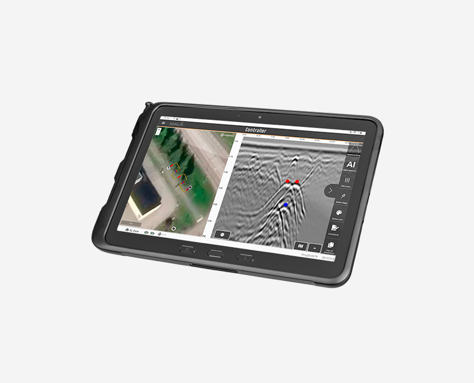
The results from a GPR investigation on roads is rather straightforward. Data can be analysed in different types of software (for example ReflexW and GPR-Slice) where the data is processed and interpreted according to application. Layer data is most often presented as X, Y and Z, where X and Y gives the positions and Z the depth to the interpreted layer. This data can be viewed superimposed on maps with easy color scheme representing the layer thickness interpretation. The example image shows a road investigation of asphalt. As seen in the mid parts of the profile, asphalt has been added on several occasions.

GPR investigation results using multichannel array measurements
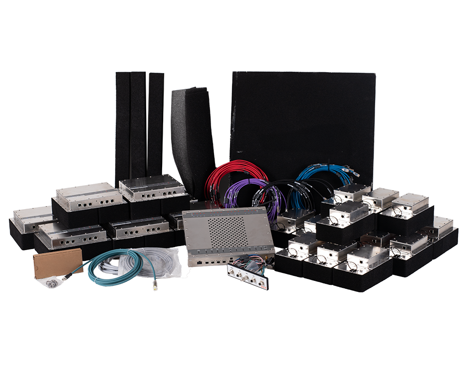
Road investigations can sometime benefit from multichannel array measurements. This will give a 3D visualisation of the road. Instead of making several runs with a single radar antenna you can measure several parallel profiles simultaneously (the technique is explained in Application Area Utilities). Guideline Geo provides several different options of multichannel arrays, for the best possible solution to your application.

In the image below a multichannel array investigation is carried out with MIRA HDR. 4 parallel utility lines crossing the road together with one utility along the road construction is clearly seen. The multichannel data also reveals different structure (due to stones, boulders) in the road embankment.

Things to think about: GPR for Road Investigation
Guideline Geo has several solutions for investigation of roads, both for road embankments and its internal layering and the conditions beneath the road structure.
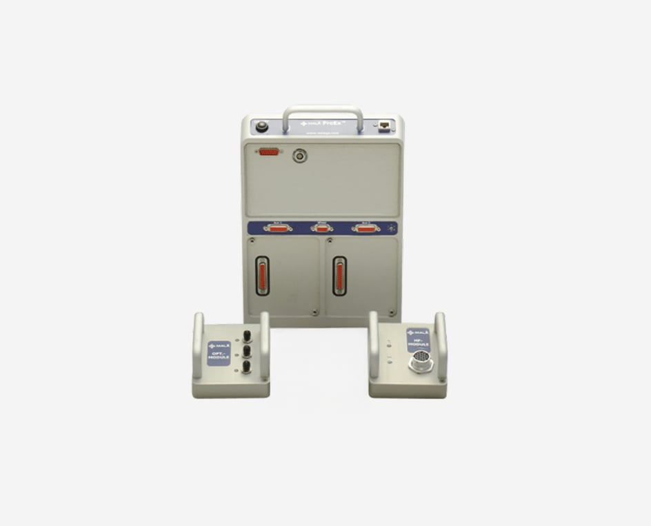
Most often road investigation comprises investigation of thin layers of asphalt to deep road embankment constructions. With a MALÅ ProEx GPR system several antenna frequencies (from low to high, up to 8 antennas) can be utilised simultaneously, saving time and costs. The system is very robust and has a number of accessories suitable for road measurements including the convenient Road Cart upon which 3 different shielded antennas can be mounted. Interpretation is efficiently done with software solutions such as MALÅ Vision or Reflexw.
If you are going to work on larger areas, instead of single lines, and are interested in utilities, rebars in concrete roads, voids and other discrete targets within the road embankment or on runways, Guideline Geo´s multichannel MIRA-systems, MIRA HDR and MIRA Compact, are a suitable solution giving you multiple, close-spaced parallel lines (total number varies by MIRA model) in one single swath, perfectly positioned and results easily processed for 3D views in MALÅ Vision.
If your main application is estimation of thicker layers, the total road embankment and the geology underneath the road structure, Guideline Geo´s GX system with antennas from 80 to 750 MHz can be suitable. This is the easiest to use system with its Wi-Fi option, making all cables unnecessary. Interpretation is efficiently done with Reflexw or MALÅ Vision.