Utilites Mapped with GPR and MALÅ Vision
Discover advanced GPR solutions for precise utility locating and mapping; prevent costly strikes and ensure site safety.
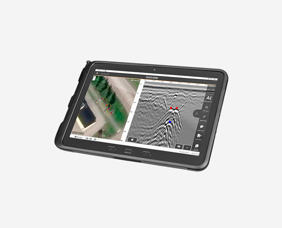
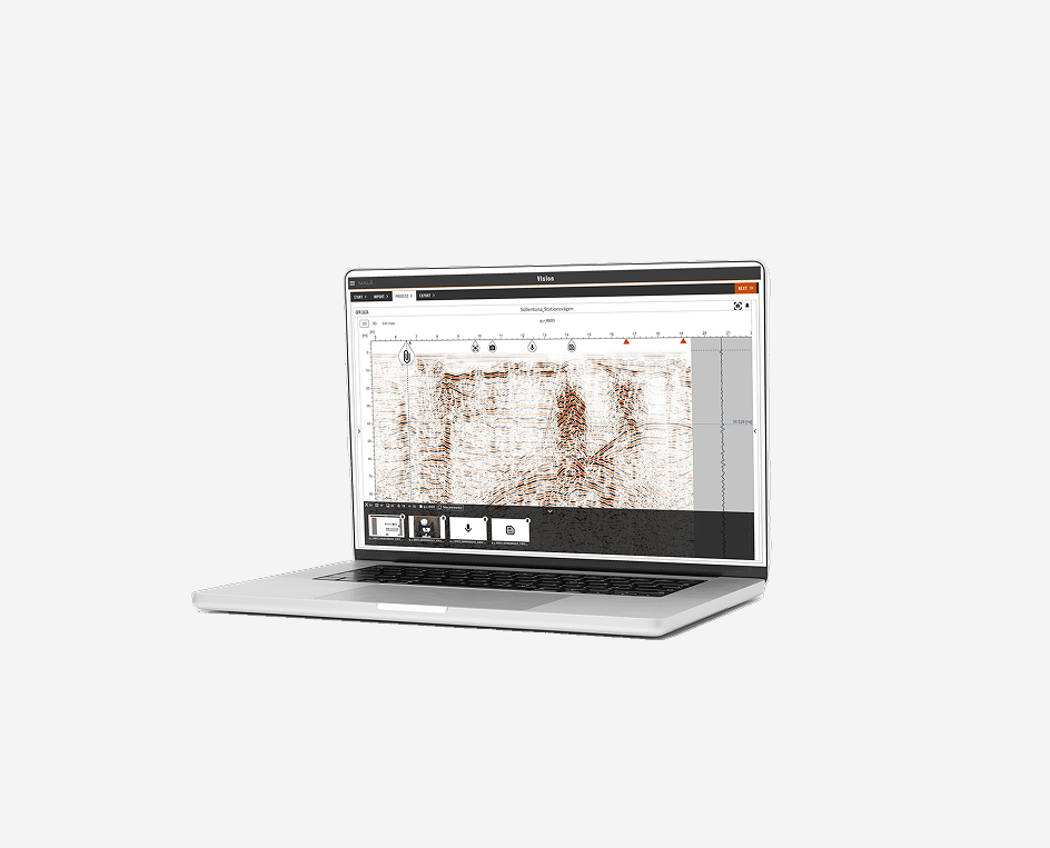
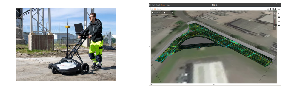
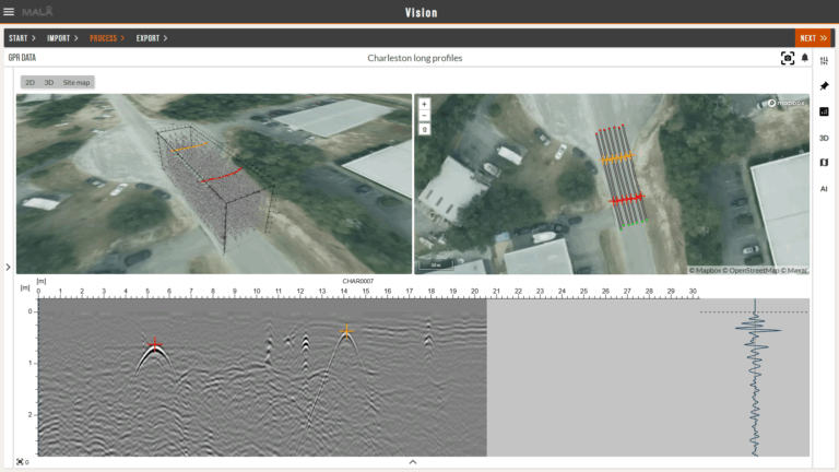
Above: A view of how mapping utilities can look when viewed through MALÅ Vision post-processing software.
Preventing Risks with Utility Locating
The ground beneath our feet in urban areas inevitably gets more and more congested over time with infrastructure comprising both underground structures and utilities. This, together with increasing urbanization and regeneration, aging infrastructure, climate change and flooding, are fueling a need for utility locating and better understanding of the subsurface conditions.
This is no easy task; utilities can, for example, consist of pipes, conduits, cables, tanks of differing material, size, and age. These utilities are buried at different depths in the ground which can be made up of widely varying natural and imported materials. The knowledge of both the location and depth can be lacking, due to obsolete, inaccurate, or non-existent subsurface maps. This lack of knowledge can lead to excavation or cutting in the wrong places, which in turn can cause serious damage, be dangerous, costly, and result in huge time delays.
So, knowing the locations of underground utilities can:
- Prevent injury and death to workers
- Reduce public inconvenience from outages
- Avoid additional and unnecessary costs
- Avert or minimize lawsuits or problems following negligence
- Avoid unnecessary loss of reputation
Ground Penetrating Radar (GPR) for Utility Locating
Most often GPR can be used as an efficient investigation technique to investigate utilities, without digging or drilling.
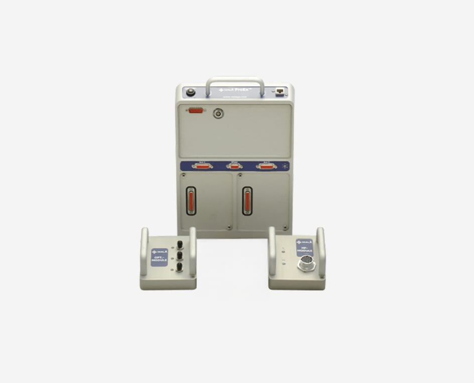
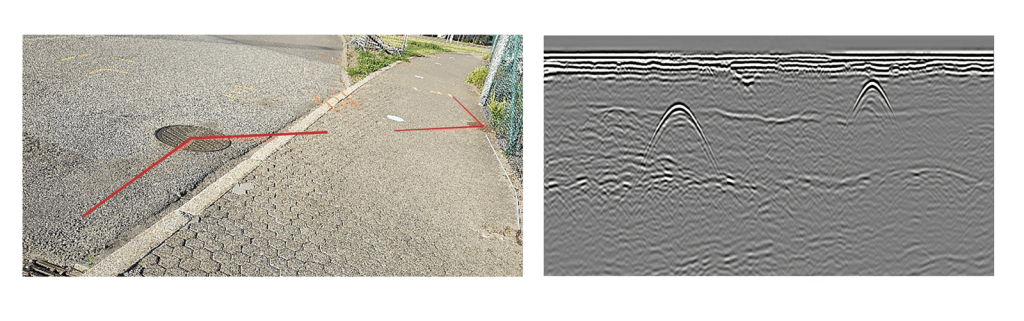
The transmitter and receiver are often put in one antenna box for easier handling in the field but can also be housed in separate units. Discrete objects, such as utilities, typically produce characteristic features, so called hyperbolas, in the resulting radargram.
What frequency to use for the GPR investigation depends on the type of utility application and the required resolution and depth of your survey. For utility locating and mapping, frequencies of around 160-600MHz are usually suitable; see table below.
As seen in Table 1, the resolution changes with antenna frequency. This is also true for increasing depth, meaning that objects need to be larger, at depth, to be detectable.
| Antenna Frequency (MHz) | Suitable Target Size (m) | Approx. Depth* (m) |
| 160 | 0.16 | 12-15 |
| 450 | 0.06 | 4-5 |
| 600 | 0.04 | 3 |
| 750 | 0.03 | 2-3 |
*Geological conditions determine the detection depth. Conductive soils significantly limit detection depth. These figures represent typical ground conditions. Other media, such as clean sands and frozen ground, offer significantly better performance.
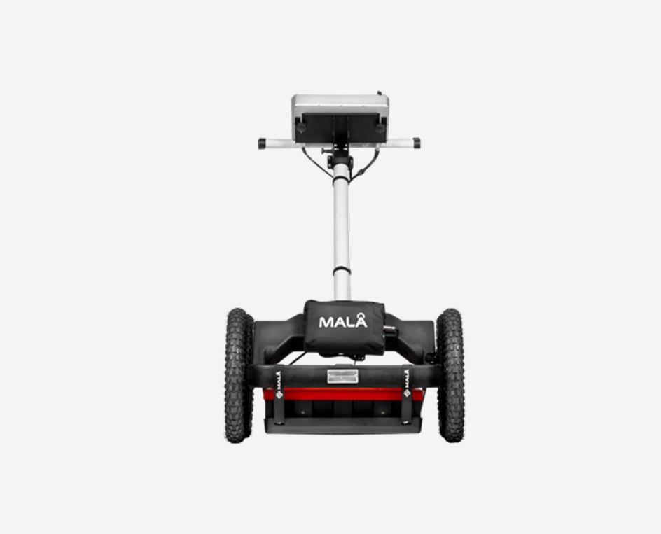
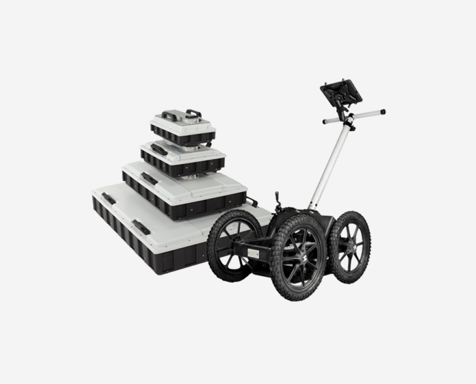
GPR measurements are most often done by pushing the antennas in a cart along a predetermined line on the ground. During an investigation, the position of the GPR antenna can additionally be tracked by an external or internal GPS.
Single-Channel and Multichannel Array GPR
A 2D single-channel GPR system can only map a single subsurface profile with each pass. In order to better understand the size, shape and distribution of buried structures and objects it may be beneficial to build a 3D data volume where the GPR data can be used to create informative maps from various depths of the subsurface; there are two approaches to this.
The first is to build up a data block with a single-channel instrument collecting data at relatively coarse spacing (say 0.25m or 0.5m line intervals) in one or, ideally, two directions, orthogonal to each other.
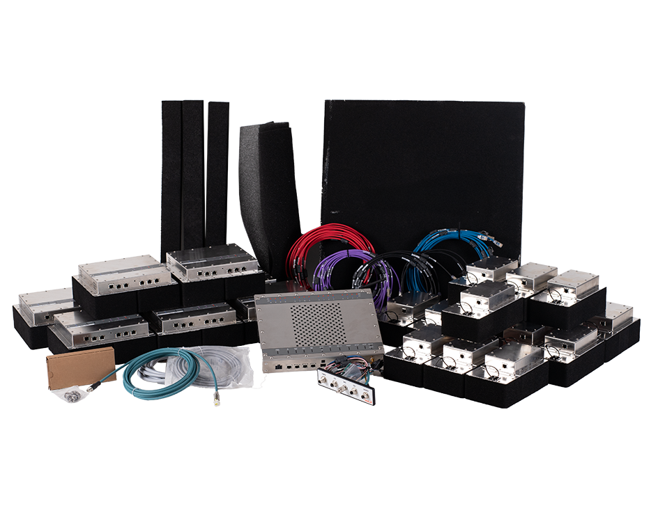
The second approach, which will offer extremely high-resolution information of the subsurface, is to collect a “true 3D” data set, where the multiple parallel lines must be collected with extremely dense transect spacing. The ideal spacing is related to the frequency of the antenna and for a typical utility system this would be less than 0.1m. With a single-channel system, this approach would result in a time-consuming investigation with difficulties in positioning each individual line correctly. Instead, multi-channel solutions have been developed where an “array” of several transmitters and receivers provide the closely spaced data channels and precise positioning required for “true 3D” survey. It should be noted that these multi-channel array systems are distinct from instruments with multiple channels collecting fewer, more widely spaced profiles at once, or just multiple frequencies along the same line. As the true 3D systems create a data volume made up of extremely dense profiles, where line spacing and trace interval are similar, the survey swathes need only be collected in one direction.
Single channel 2D GPR is often sufficient for smaller utility locating and mapping projects, but when the investigation area gets larger, and the layout of the buried utilities gets more complicated, a multichannel solution can be a more efficient option.

Projects Marked Directly on Site – Mark out/Avoidance
When working with single-channel GPR, over good ground conditions, the identification of hyperbolas can often be done directly at the site, marking their position and/or depth on the ground surface. The location of the utility is set at the hyperbola’s highest point and all Guideline Geo single-channel GPR systems have a back-track function to simplify the work of directly marking out the detected utilities.
Projects Analysed After the Survey – Post-processing
GPR equipment delivers interpretable, real-time, images of the subsurface. However, to create clearer and less ambiguous subsurface images, post-processing of data is necessary. This is especially true when performing 3D GPR array projects in highly congested subsurface areas. In general, post-processing will help to remove noise, fixing errors, create better depth conversions and enhancing features. When high accuracy of results is needed, post-processing of data is essential.
Guideline Geo has created MALÅ Vision to help with your post-processing needs. MALÅ Vision comes in two different versions. MALÅ Vision Web helps you to make immediate analysis, processing, interpretation and reporting of your data. MALÅ Vision Desktop has more processing power, enhanced tools and interpretation capabilities. MALÅ Vision Desktop is recommended for larger, more complex projects and for all MALÅ MIRA users. There are many options available for your post-processing needs, please contact us for more information.
Example of utilities mapped with Guideline Geo’s multichannel MIRA Compact system