Welcome to the ABEM Vs30 Guidance Tool
This step-by-step guide will take you through the process of collecting quality seismic data to undertake Vs30 analysis. This guide is optimized for mobile devices.
NOTE: Vs30 surveys require 4.5Hz vertical geophones
With the set-up wizard on the screen of the instrument, click start, below.
>> START <<
Settings and field procedures are based on recommendations published by Park et al.
Click for more information
Step 1a: Instrument Settings
Select 24 channels in the Terraloc Set-up Wizard
(use single cable option for 48 channel instruments)
Select Vs30 from the drop-down menu
Select the green “NEXT” button
Step 1b: Instrument Settings
On the second page of the Terraloc Set-up Wizard, select 2m geophone spacing and hammer source.
Press “OK”
Step 2: Cable / Geophone Layout
This is a generic layout for a Vs30 measurement with 24 geophones.
If you have a 48 channel instrument, use only the first cable to provide 24 channels.
Geophone spacing should be 2 metres
Step 3a: First Shot Position / Trigger Connection
Place shot plate 48m from Geophone 1
Trigger connection via trigger wire
Place a spare geophone next to the shot plate and connect to the trigger reel.
The far-end of the trigger reel should be plugged into the “Analog. Trig In” trigger connection on the instrument end-panel.
It is possible to use a wireless trigger connection, see here for more information.
Step 3b: Set-up Layout Geometry
Open the Layout Geometry window by pressing 6 on the front panel of the instrument
Enter shot position x: -48m
Step 4: 1st Shot
Example shot record from a -48m off-end shot:
Data look different? Try our Troubleshooting Guide
Step 5: 2nd Shot
Update shot position to -24m in Layout Geometry
(press 6 on the front panel)
Example shot record from a -24m off-end shot:
Data look different? Try our Troubleshooting Guide
Step 6: 3rd Shot
Update shot position to -12m in Layout Geometry
(press 6 on the front panel)
Example shot record from a -12m off-end shot:
Data look different? Try our Troubleshooting Guide
Step 7: 4th Shot
Update shot position to -2m in Layout Geometry
(press 6 on the front panel)
Example shot record from a -2m off-end shot
Data look different? Try our Troubleshooting Guide
Step 8a: 5th Shot
Place shot plate 2m from the last geophone
Enter shot position as 48m in Layout Geometry
(press 6 on the front panel)
Remember: the distance entered is from the first geophone (0m in the spread)
Data look different? Try our Troubleshooting Guide
Step 8b: 5th Shot
Example shot record from a 2m off-end (48m) shot:
Data look different? Try our Troubleshooting Guide
Step 9: 6th Shot
Update shot position to 58m in Layout Geometry
(press 6 on the front panel)
Example shot record from a 12m off-end shot:
Data look different? Try our Troubleshooting Guide
Step 10: 7th Shot
Update shot position to 70m in Layout Geometry (press 6 on the front panel)
Example shot record from a 24m off-end shot:
Data look different? Try our Troubleshooting Guide
Step 11: 8th Shot
Update shot position to 94m in Layout Geometry (press 6 on the front panel)
Example shot record from a 48m off-end shot:
Data look different? Try our Troubleshooting Guide
Step 12: Transfer Data
Using Android device?
Connect your phone via USB to the Terraloc Pro 2 and allow access on your device.
The Terraloc will see your device as an external storage location, use the CTRL + SHIFT + LEFT ARROW shortcut to access the file explorer and move files across.
Using ALT + TAB will take you back to the Terraloc Pro 2 software.
Using USB drive and PC
Connect your USB drive to the Terraloc Pro 2 and this will be used as the destination for the Quick Backup function on the instrument.
Step 13: Process / Analyze Data
Processing requires 3rd party inversion software such as Geogiga
Step 14: Generic Processing Workflow
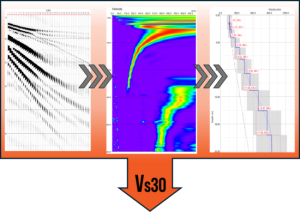
The 8 shots are processed individually, each creating a velocity model, these results are correlated to generate a combined velocity model, summarised by the Vs30 value.
IMPORT DATA
& QUALITY CHECK
|
GENERATE
DISPERSION CURVES
|
PICK THE LINE
OF THE CURVE
|
RUN INVERSION ON
THE PICKED CURVE
|
COMBINE RESULTS TO GENERATE
AVERAGE VELOCITY MODEL
|
COMPARE Vs30 VALUE
AGAINST AGREED STANDARD
(after BSSC, 1997*)
*Building Seismic Safety Council (BSSC), 1997, NEHRP, recommended provisions for seismic regulations for new buildings, Part 1-Provisions (FEMA Federal emergency Management Agency 302), 290 p.